Heater Transistor Replacement

Frequently asked technical questions and common modifications/improvements
Post Reply
User avatar
mat_fenwick
Moderator
Posts: 7326
Joined: Tue Sep 20, 2005 4:08 pm
Location: North Wales
x 19

Heater Transistor Replacement

Post by mat_fenwick »

I'll start off by saying that I haven't actually known the transistor fail, but I've heard that if it does the likely failure mode is full on. If you have checked that the blower motor(s) has a 12 V feed to it, and that the earth is good to the control PCB in the cabin, the fault is likely to lie with the transistor module in the blower motor housing.

This is accessed by removing the windscreen wiper and the scuttle vent panel. The module is on the rear of the housing with a 4 terminal connector leading to it. If you temporarily earth the LH terminal and it works, the fault lies elsewhere. It can be removed without taking out the complete housing, but unless you have AC it's easy enough just to take out the whole assembly, then you can see what you are doing.

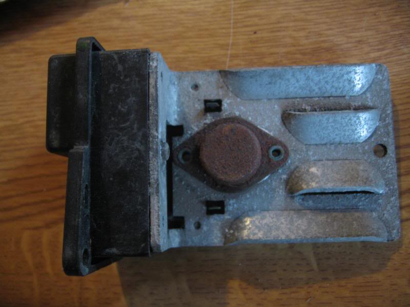
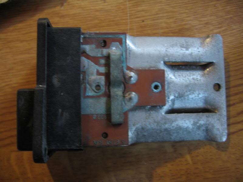
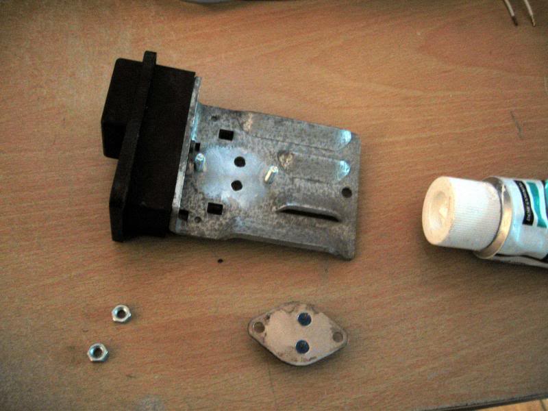
This is the removed module, looking typically rusty:

Image

Image

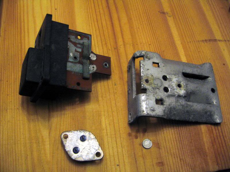
Underneath the sprung contact in the middle is a metal disc - corrosion often builds up between it and the transistor. Drill out the two rivets securing the transistor to the PCB and desolder the transistor.

Image

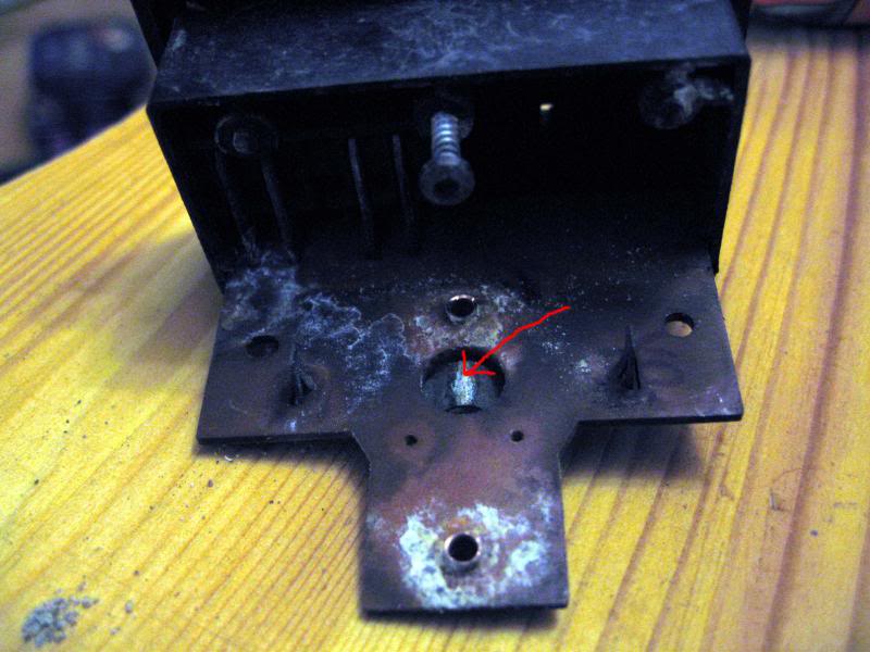
Here you can see the sort of corrosion which gives a poor contact:

Image

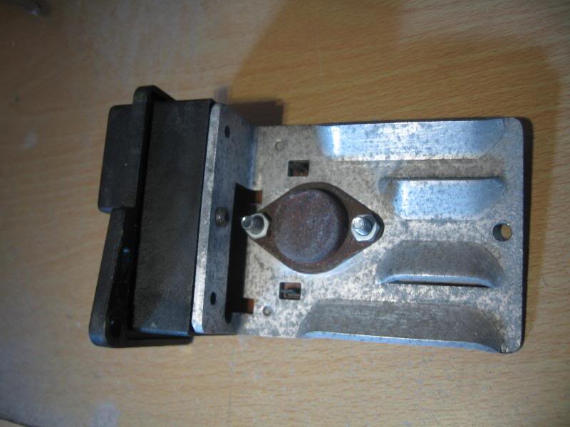
Clean up all contact surfaces and reassemble the disc, heatsink and PCB. I use a smear of silicone grease to help prevent further corrosion. Apply a thin layer of heat transfer compound between the transistor and the heatsink - a thick layer will actually insulate it. Put the transistor in position and shuffle it slightly to ensure good thermal contact. I've used bolts to fasten it back but rivets can be used if you wish.

Image

And here is the finished article, ready to go back in the car:

Image

The transistor used is a Darlington type, which is basically two transistors coupled together in one casing, sometimes incorporating additional components. For this reason, typical transistor tests may prove inconclusive, but you can check for short circuits between the two pins and the case. Full testing would need to be done by building it into a circuit, so it may be just as easy to try cleaning the contact surfaces as above.

If the transistor does need replacing, there are a list of suitable part numbers in this thread.
Image

1993 1.9 TZD Turbo Estate
1996 3.9 V8 Discovery
1993 VW LT35 campervan
1985 Hyundai Stellar V8
2016 Hyundai iLoad
User avatar
mat_fenwick
Moderator
Posts: 7326
Joined: Tue Sep 20, 2005 4:08 pm
Location: North Wales
x 19

Re: Heater Transistor Replacement

Post by mat_fenwick »

For completeness, the internal schematic of the FW26025A1 transistor is below:
BX FW26025A1 heater transistor.jpg
BX FW26025A1 heater transistor.jpg (23.35 KiB) Viewed 5025 times
Others will likely have a similar internal layout.

It's just struck me what the metal disc is probably for - thermal protection. I would guess it is made from a low melting point metal, so that if the transistor got too hot (motor seizure hence no cooling air) it would melt and break the circuit. I certainly can't think of any other reason for it to be there.
Image

1993 1.9 TZD Turbo Estate
1996 3.9 V8 Discovery
1993 VW LT35 campervan
1985 Hyundai Stellar V8
2016 Hyundai iLoad
User avatar
BX Bandit
Backslash Bandit
Posts: 2588
Joined: Thu Aug 31, 2006 7:46 am
Location: Home
My Cars: Cars
x 3

Re: Heater Transistor Replacement

Post by BX Bandit »

In cars with A/C aren't there two of these? One per fan?
1990 BX 16V Platinum Grey
1990 BX TGD White
1960 Morris Minor Clarondon Grey
1971 Triumph 2000 Auto Valencia Blue
User avatar
mat_fenwick
Moderator
Posts: 7326
Joined: Tue Sep 20, 2005 4:08 pm
Location: North Wales
x 19

Re: Heater Transistor Replacement

Post by mat_fenwick »

Based on the one car I removed the AC system from, then no! I replaced the non working module with one from a standard car, which I put a higher current capacity transistor in. I later found out that the same module is used in both AC and non AC cars though.

There must be two different types of module though - there are some wiring diagrams around which show the earth path from the base of the transistor (via the control dial wiper) routed back to the transistor module and a fixed value resistor (presumably to limit Emitter to Base current when the wiper contact is dialled to a low resistance), then joining up with the Collector earth. The only ones I've seen though don't have a resistor present, and the earth path from the control dial is simply joined to the Collector earth.

There are two manufacturers of control PCB - one with a metal variable resistance path (Chausson), the other with a carbon track (Eledasa) if I've remembered the right way round! My guess is that the carbon track version has a residual resistance which will limit the transistor Base current...just a guess though and I haven't actually investigated to prove one way or another.
Image

1993 1.9 TZD Turbo Estate
1996 3.9 V8 Discovery
1993 VW LT35 campervan
1985 Hyundai Stellar V8
2016 Hyundai iLoad
User avatar
Vanny
Merseyside resident
Posts: 3581
Joined: Tue May 17, 2005 11:48 pm
Location: BXProject
My Cars: BX 16v Ph2 - Jazz
BX 16v Ph2 - XPO
x 79
Contact:

Re: Heater Transistor Replacement

Post by Vanny »

Thermal trip would make sense, all the systems i've played with, they all have thermal trips of a similar type. They melt at around 80c i think and fail safe. They are there in case of a 'stall' incident (stick in the fan for example).

The AC cars only have one controller in my experience.
Post Reply