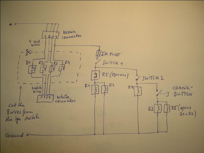
The 4 positions on the brown connector are all equally permanent +12V (switch input), the 4 positions on the white connector (behind the brown) are the switched outputs from the ign. switch to power the accessories, ignition, starter motor.
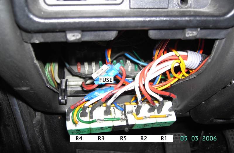
What the bx's junction box needs:
Looking at the white connector of the ign. switch (3rd row from the relays, 4th from right), pins numbered from #1 to#4 from right to left:
- Key position 1 (only accessories on, no engine): +12V only at #1 and #2
- Key position 2 (driving): +12V only at #1, #2 and #4
- Key position 3 (engine start): +12V only at #3 and #4
- Key position "off": no +12V anywhere
Pin #1 (the very right) goes to the accessories over Fuse F3,
#2 goes to the acessories over Fuse F2
#3 goes to the starter motor
#4 (the very left) goes to the fuel shutoff valve, preglow and Fuse F1 (rev. counter, etc.)